
CONFIGURATION-2
Configuration 2 reimagines structural connections through geometric innovation—eliminating separate connector hardware entirely. By integrating V-shaped punched patterns directly into the CFS channel sections, this system achieves mechanical interlocking with GFRP bars through form and geometry rather than fasteners. The result: faster fabrication, reduced component counts, and streamlined installation without compromising structural or thermal performance.
How It Works?
Component 1
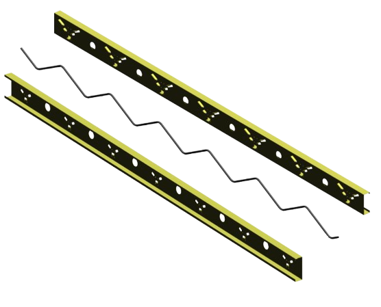
V-Punched CFS Channel Sections
Cold-formed steel channels with factory-formed V-shaped punched patterns that create mechanical interlock geometry. Precision stamping from 95% recycled steel with integrated MEP pathways.
Component 2
GFRP Zig-Zag Bars
V-shaped Glass Fiber Reinforced Polymer bars designed for geometric engagement with punched channels. Mechanical interlock through shape compatibility—no fasteners required.
Connector-Free Structural System
The punched V-pattern creates positive mechanical engagement with the GFRP bars’ V-shaped profile, locking components together during assembly and maintaining composite action under service loads. This connector-free design transfers loads through geometric engagement, eliminating thermal bridging without additional hardware.
Why Choose Configuration-2?
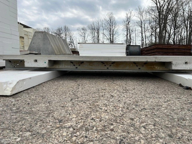
GFRP zig-zag bars are placed between two cold-formed steel (CFS) channel sections with V-shaped punched patterns that mechanically interlock with the bars. This creates an integrated assembly that structurally ties the metal studs while fully isolating the concrete wythe from the steel framing. The connector-free design transfers loads through geometric engagement, eliminating thermal bridging without the need for additional hardware.
Complete Thermal Isolation
100% thermal break achievement with ¼" separation gap—zero thermal bridging without connector hardware.
Geometric Interlocking
V-punched patterns create positive mechanical engagement with GFRP bars' V-shaped profile through form-fitting design.
Accelerated Fabrication
Elimination of connector installation step reduces panel production time. Simplified assembly: Position GFRP bars between punched channels—done.
Laboratory-Validated Performance
Proven structural capacity under ASTM E72 protocols with controlled, ductile response under extreme loading.
Sustainable Design
95% recycled steel content, 40% concrete volume reduction, and 40% reduction in life-cycle climate impact.
Cost Efficiency
Material cost savings from eliminated connectors, reduced labor through simplified assembly, and faster production cycles.
Ideal Applications
- High-volume residential developments benefiting from accelerated panel production
- Fast-track commercial projects requiring rapid fabrication and delivery
- Multi-family housing where cost efficiency drives material selection
- Modular construction integration (e.g., container hotels) demanding lightweight, precision panels
- Projects with tight budgets seeking maximum value without performance compromise
Specifications
V-Punched CFS Channel Sections
Cold-Formed Steel with Integrated Punching.
Pattern Design
Factory-formed V-shaped punched patterns at engineered spacing.
Manufacturing
Precision stamping creating consistent interlock geometry
Material
95% recycled steel content.
Integration
Standardized profiles with integrated MEP service pathways.
Tolerances
Dimensional tolerances maintained to ±1/8".
GFRP Zig-Zag Bars
½" Nominal Diameter
Configuration
V-shaped configuration designed for geometric engagement with punched channels.
Material
Glass Fiber Reinforced Polymer (ASTM D7957).
Thermal Conductivity
0.25–0.35 W/m·K (eliminating thermal bridging).
Engagement
Mechanical interlock through shape compatibility, not fasteners.
Anchoring
Embedded concrete anchoring developing shear capacity.
Connector-Free Integration
No Separate Hardware Required
Replacement
Punched pattern geometry replaces VRE-connector hardware.
Engagement
Direct GFRP-to-channel engagement through form-fitting design.
Assembly
Reduced component inventory and assembly steps.
Quality Control
Simplified QC with fewer parts to inspect.
Thermal Advantage
½" separation gap—100% thermal isolation.
R-24 minimum (R-40+ achievable).
30% improvement vs traditional precast.
Zero thermal bridging.
0.25–0.35 W/m·K (vs. 45–60 for steel).
Structural Performance
V-shaped GFRP geometry for in-plane forces.
Multi-story load capacity from container modules.
Maintained under service and ultimate loading.
Laboratory-validated under ASTM E72.
Controlled, ductile response.
Energy Performance
Superior thermal efficiency reducing operational energy.
Enhanced building envelope targeting LEED® v4.
Durable, recyclable materials at end of service life.
Manufacturing & Installation
Factory-controlled precision meets installation efficiency
Accelerated Fabrication
Elimination of connector installation step reduces panel production time—approximately 2 hours saved per panel.
Simplified Assembly
Position GFRP bars between punched channels—done. No fastener installation, torque verification, or alignment procedures.
Component Optimization
40% reduction in component count with streamlined inventory and reduced quality control checkpoints.
Sustainability Leadership
CFS channels from recycled steel
vs. conventional precast systems
Life-cycle climate impact reduction
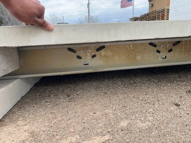

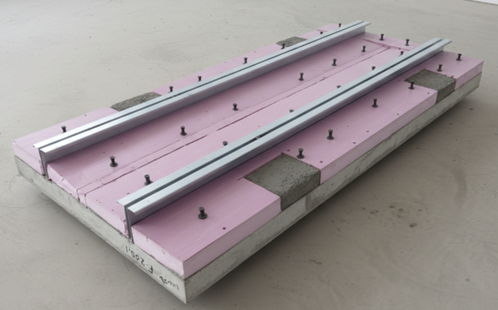
Key components
FRP Bars and Custom-punched Metal Studs
Forging these advanced components directly into the concrete, we’ve created a panel that is significantly lighter but incredibly stable.
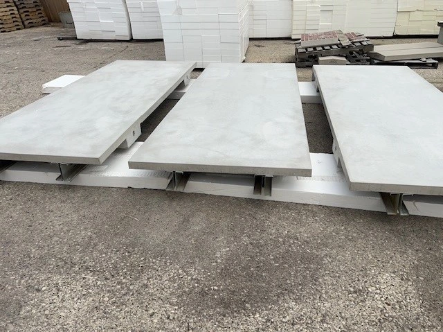
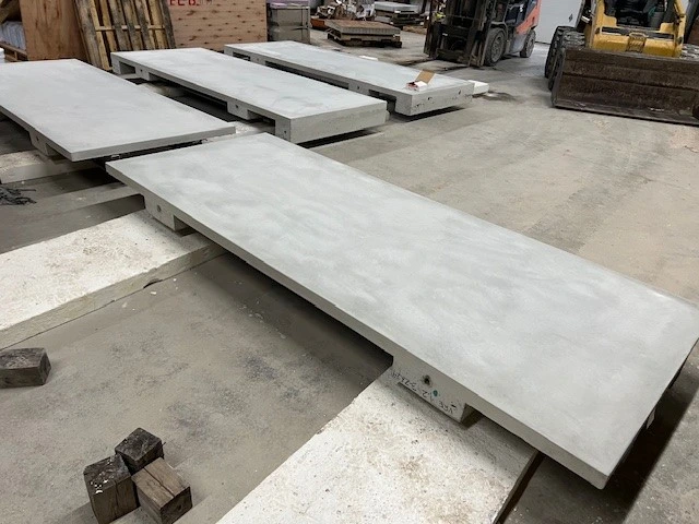
With and Without Insulation layer
Whether you choose a configuration with or without insulation, the exterior dimensions remain exactly the same. You get the thermal efficiency you need or the raw structural power you want—all within the same consistent, easy-to-install footprint.
Publications (Coming Soon)
Technical Whitepaper
Comprehensive analysis of our panel system technology
Technical Whitepaper
Comprehensive analysis of our panel system technology